What This Means for Your Project
The capability details below are intended to help engineering, quality, and sourcing teams evaluate execution reliability.
Electrical and Mechanical Test Matrix
Testing resources should be presented as a decision matrix that maps requirement type to verification focus.
Electrical Baseline
Contact resistance, insulation behavior, and withstand checks provide early pass/fail confidence.
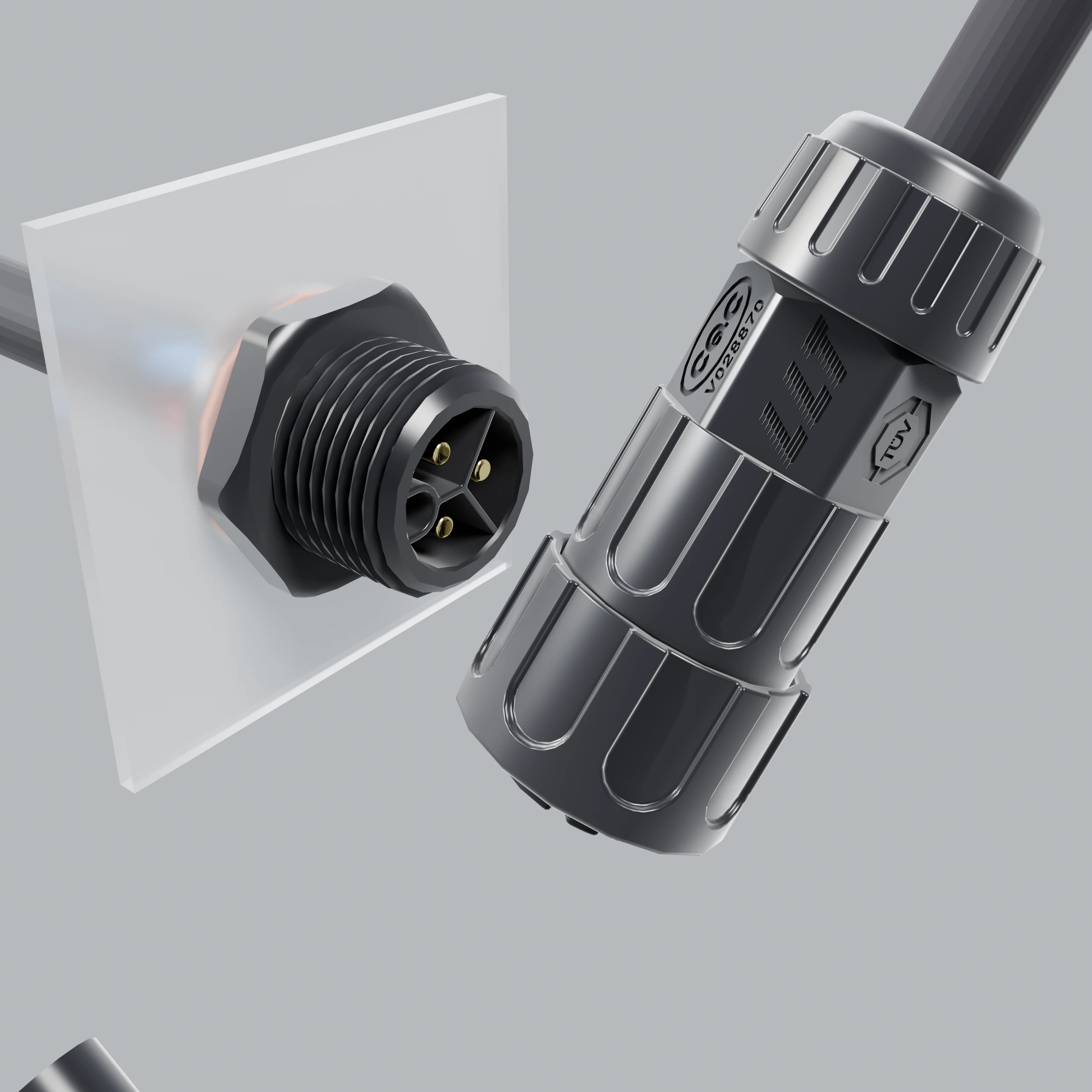
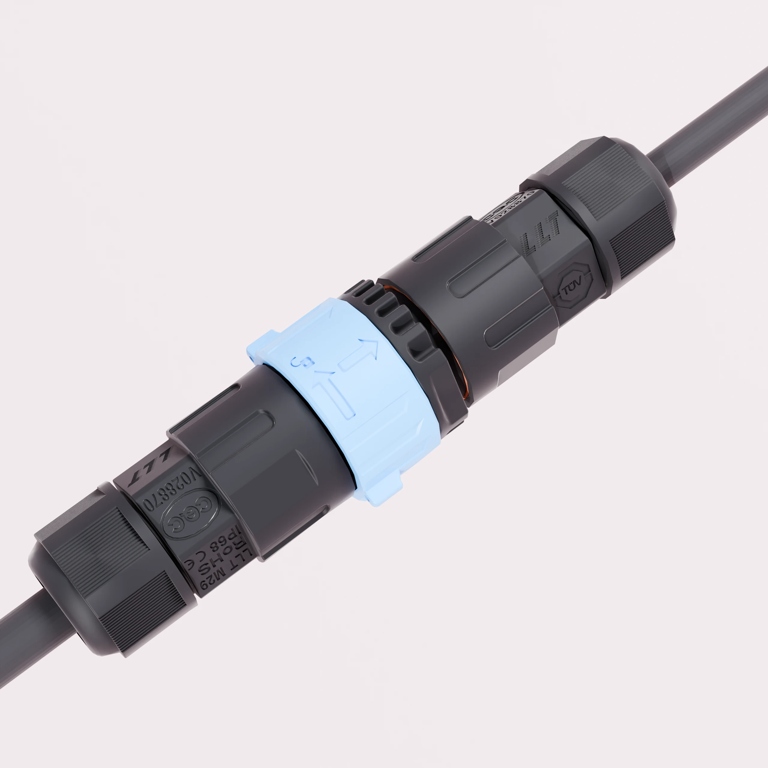
Mechanical Durability
Insertion/extraction force, vibration, and locking behavior checks reflect real use stresses.
Assembly and Harness Checks
Cut/strip quality, conductor state, crimp/solder integrity, and sequence consistency protect harness reliability.
Validation Matrix
| Check Item |
Verification Focus |
| Insertion and extraction force |
Mating stability and operator-side consistency |
| Contact resistance tracking |
Electrical path quality under cycle and load conditions |
| Insulation / withstand checks |
Electrical safety margin before release |
| Vibration and lock behavior |
Connection integrity under dynamic movement |
| Harness workmanship checks |
Cut, strip, conductor, crimp, solder, and sequence quality |
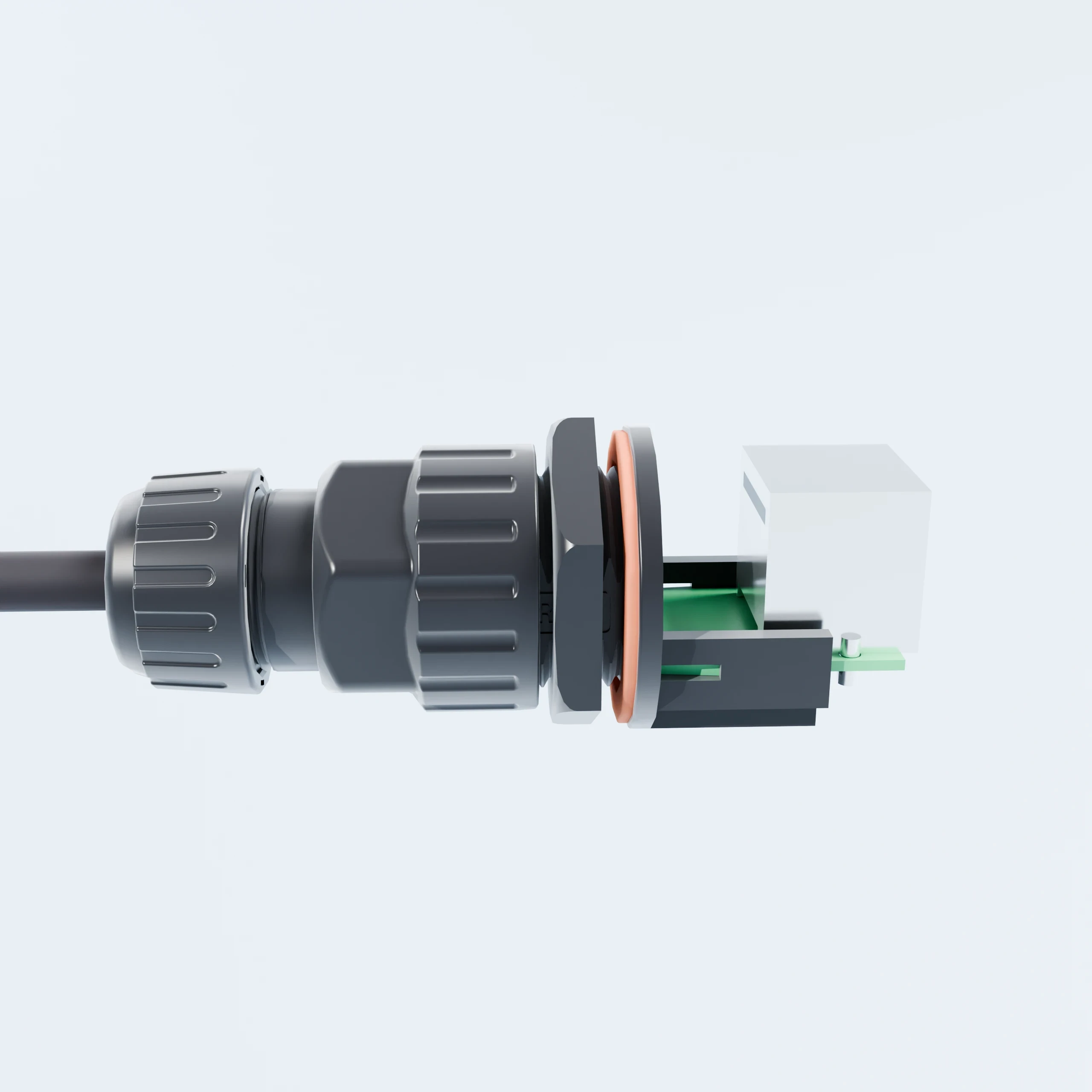
Critical Control Points
- Pin insertion force
- Mating-gap verification
- Molding completeness
- Lock depth
- O-ring compression state
- Terminal contact resistance
- Pressure / insulation / withstand checks
- Cut length
- Strip length
- Conductor condition
- Color / sequence consistency
- Crimp quality
- Solder quality
- Electrical validation
- Batch archive and release logic
- Abnormal isolation + CAPA + re-verification
Need a test checklist mapped to your project target?
Contact LLT Connector to define baseline tests and acceptance thresholds.
Define Test Checklist